Open-source Fan Controller
Automatic cooling solution for a 15U rack in my living room.
What do you think is the biggest problem with having a home lab in your living room? Does it take up too much space? Maybe. Eat up a lot of money? Noooo…never. For me, it’s heat and noise management.
When I started with a firewall, an 8 port switch and a NAS, I never imagined having to worry about heat. A few years later, with a 15U rack, 4 servers and a bunch of other added equipment, managing the temperature is an issue.
Since getting my rack, I obsessively looked for an adequate cooling solution that didn’t make too much noise. First I had 2x 120 mm Noctua fans (top and bottom). As my homelab grew, I needed more airflow. That led to a little DIY modification. We had to cut a hole on the (solid) back panel to accommodate a 200 mm Noctua fan. Since they were all PWM controllable, I always wanted something to adjust them based on the temperature. I was experimenting with NodeMCU boards and directly driving fans, but that wasn’t enough.
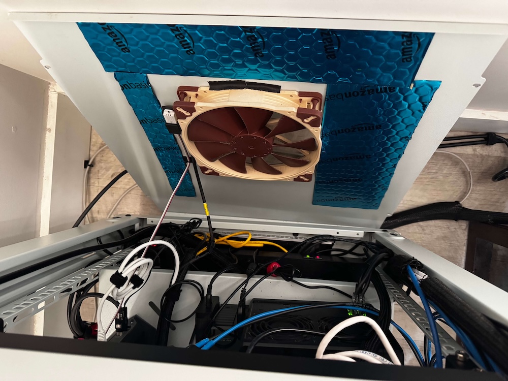 Rear Noctuafan on my homelab rack
For a long time I used Noctua NA-FC1 controller and just manually adjusted fan speed if, for example, if I had a visitor or I wanted to watch a movie. Obviously it wasn’t too sophisticated, but it worked. However sometimes I forgot to turn the fans back up, risking overheating. Also, I couldn’t see if a fan failed. There was a lot of room for improvement. I almost gave up, but after a year I found the open-source fanpico project.
Designing my own solution
As an engineer I wasn’t scared of electronics, however I never made anything this complex. It was my first attempt with soldering. I treated it as a project that included researching parts, collecting the type of fans I would use, their specifications, and how I was going to assemble them and case design.
Originally I wanted a 1U (half width) box that didn’t take too much space. Turns out, the small size was too much of a constraint. In my previous attempt I used 5V fans, so I had to buy a few extra pieces. (Most of the computer fans are 12V, but I used a USB-A hub to power mine before). Luckily I was able to turn this around and use the extra adapters to drive an LED controller.
After carefully piecing everything together, I had to solve a “chicken and the egg”- esque problem. Without a case, I had no way to imagine how to lay out the parts. I couldn’t figure out the cable lengths, orientation…without the parts, I couldn’t design the case. Like other problems in life, you just have to start somewhere.
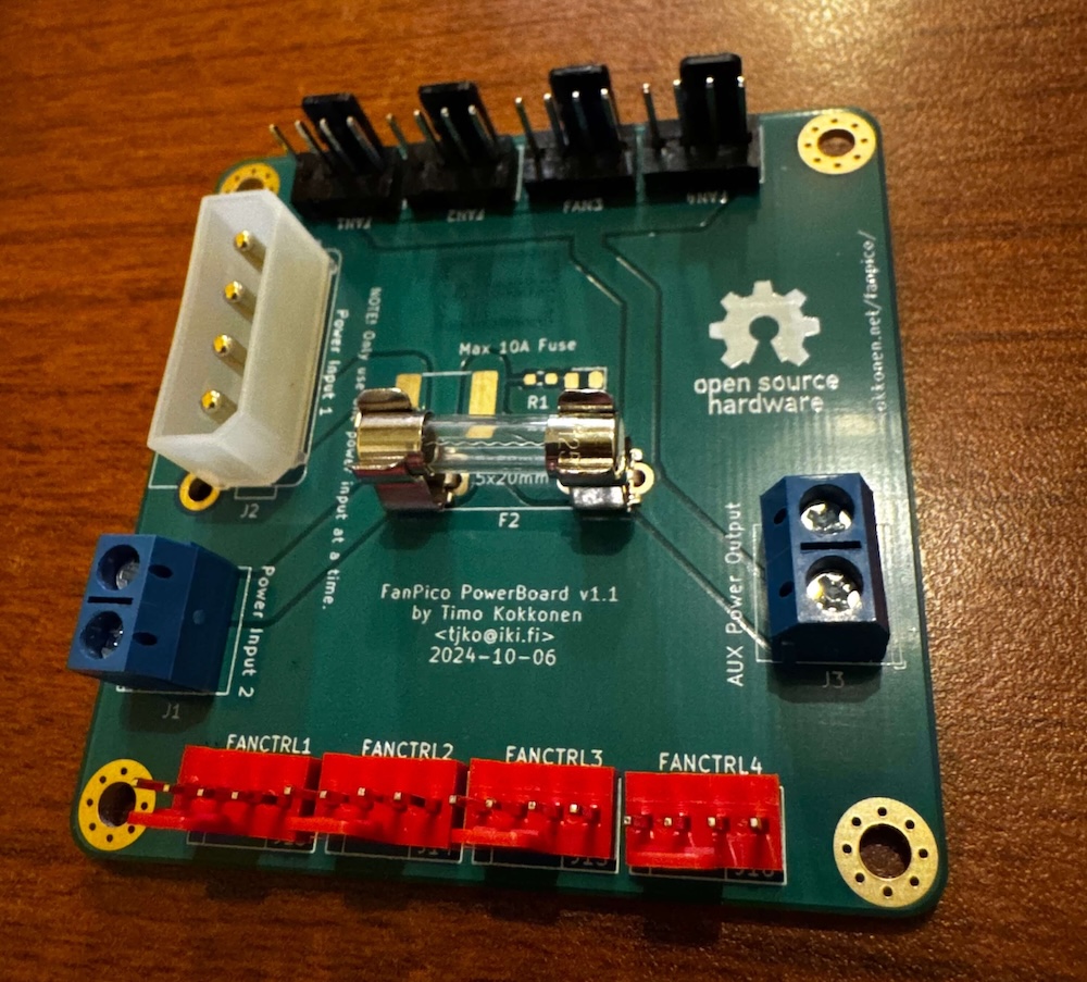
Because I wasn’t sure about my soldering skills, I used the 5V power board as a practice piece. After that I was able to do a cleaner job on the main board. I have to admit, it was pretty relaxing. Sometimes it just feels good to create things with your hands. Having the finished soldered parts in my hand allowed me to start designing the case layout.
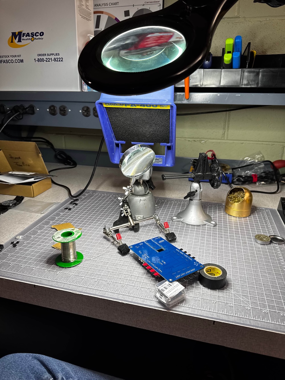 Soldering the main board
1U defined the height, the 5V converter got placed on top and because I didn’t want to over complicate things with fan connectors. I just left a bigger hole to route out cables at the back. Since the board can handle 8 fans and I only used 4, I decided to add a small, 40 mm internal fan. I made 3 revisions of the case to fit every piece and make it as compact as possible. I decided to order another power board to use 90 degree (angled) fan connectors and reduce the height.
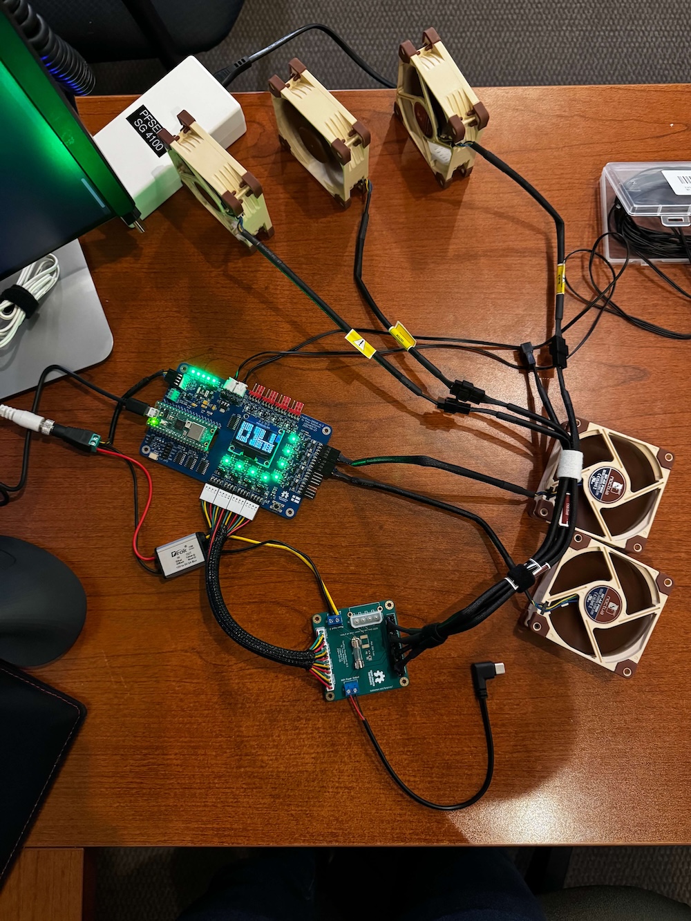
As I mentioned, because I had enough 5V power available, I added a USB-C (power only) cable to integrate a dig2Go LED controller. What is a homelab without some RGB lighting, right? It is not directly controlled by the fanpico board, Home Assistant calculates the average temperature values based on all of the sensors and changing the color (deep blue > teal > green > orange > red order).
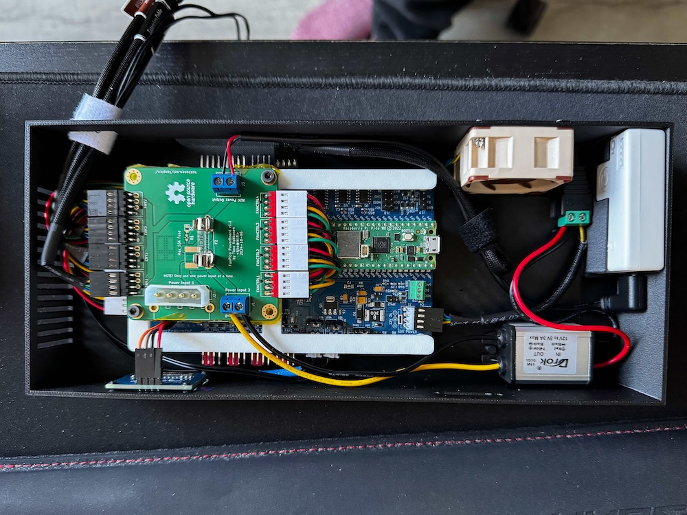 Final assembly of the rackpico in a 3D printed case
Experience
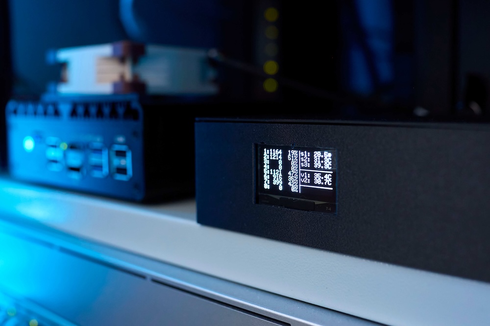
In general, I am really happy with the setup. Small features like the OLED display help to gauge the state of the whole rack. I like flexibility, the temperature sensor choice, the customizability of the virtual sensors and open-source nature. If I am worried about overheating or just want to check on my rack, I can do it from Home Assistant or just from the web UI. The fanpico project is regularly updated, adding new features like SSH connection, which allows (easier) on-the-fly changes.
Final words
The fanpico project is perfect if you want to customize fan curves in your PC, but with a little bit of tweaking, it can be used for other purposes. Any place where you need temperature controlled fans, monitoring and even Home Assistant integration.
Parts, diagrams and further information can be found on the fanpico GitHub repository.